Mechanical System (Link to GrabCAD)
Summary
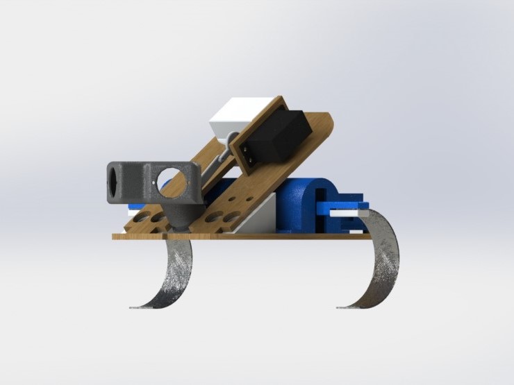
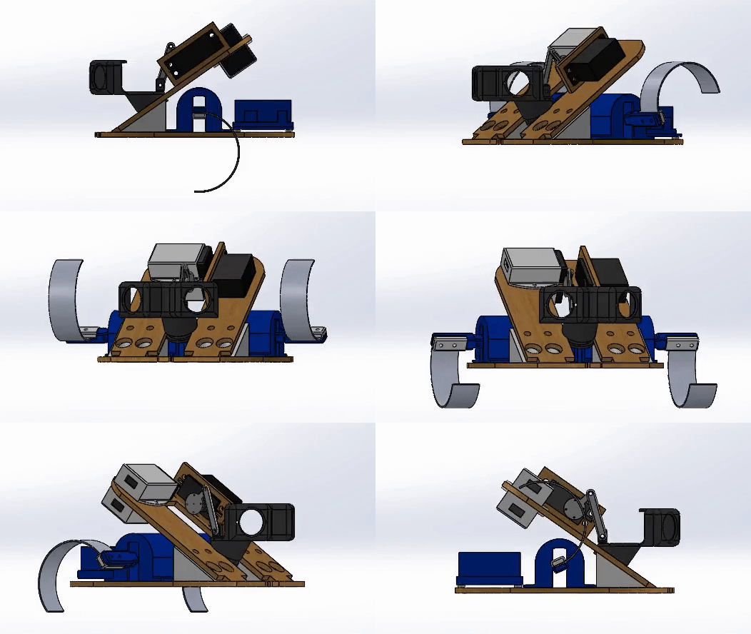
The robot is built to look and act similarly to a hermit crab. It has a shell that hides its electronics, and two curved legs to drag itself forward with. If picked up, its head will retreat into the shell until it is put back down. The basic design is built from 2 base plates that hold all the components of the robot. These components sit in snug 3D printed mounts. One plate is mounted to the other at an angle with 3D printed triangular pieces. Two large DC motors drive semicircular aluminum sheet legs, and two caster wheels also support the robot. A servo motor and linkage system can retract the crab's “head” along a slot slider mechanism.
Base Plates
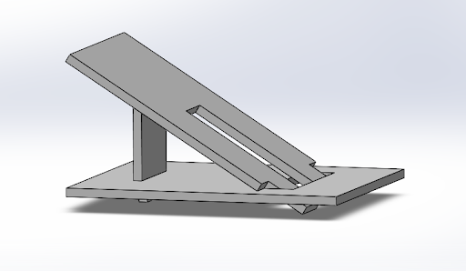
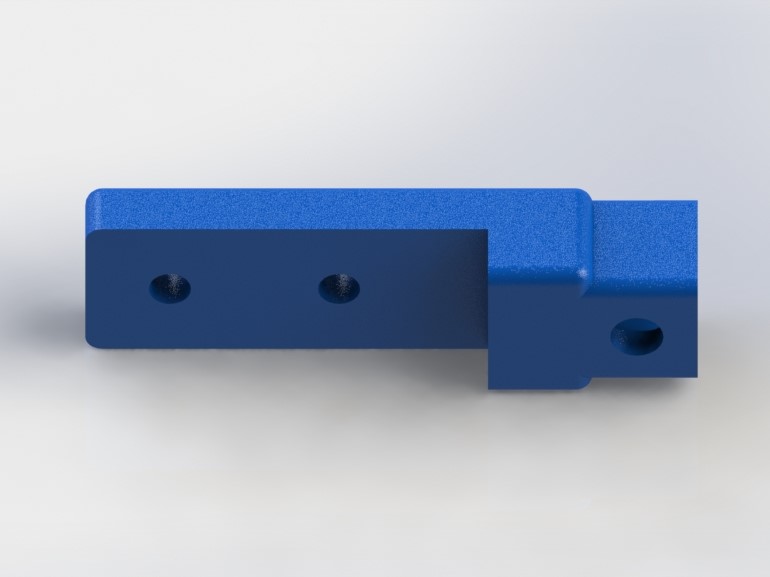
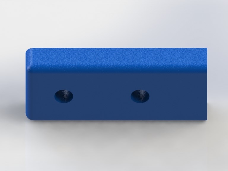
The angled design for the base plates was chosen to optimize space usage and allow the shell to cover a significant amount of the electronics without interfering with the legs. The angled plate also lets the slot slider move at an angle, making it easier to retreat into the shell. The plates were laser cut from Eucaboard, which is strong yet light, to minimize the weight of our robot. The plates are held together and at an angle using two 3D printed triangular mounting blocks. Each block has two screw holes for each plate, and holds the top plate at the ideal 35° angle for the head to be parallel to the ground. The triangles are large since they are the only support for the top plate and hold the robot together.
Movement
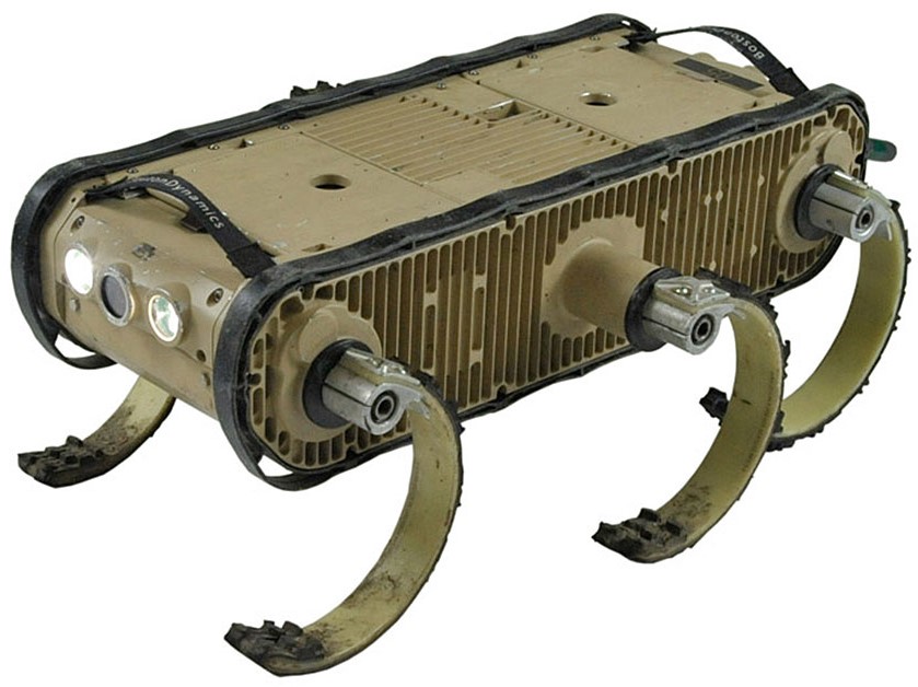
The movement of our robot was inspired by the R-Hex robot. We have two curved legs made of sheet metal with added traction to move the robot forward by using the compliance in the shape to spring the robot upwards and forwards. We chose this over a crawler mechanism because we wanted an organic movement (no wheels) but with less motors and higher speed. A crawler mechanism of this type would have two legs which each have two motors: one for the "hip" joint and one for the "knee" joint. This makes the design significantly bulkier and heavier and has more room for error. Crawler mechanisms are also often slow because of this. With the R-Hex leg design, the robot can be operated off of just two motors and they can spin full speed all the way around to enable quick motion. The compliance of the legs also means the robot can traverse over small obstacles.
Because we chose to use only 2 legs instead of 6 like the original R-Hex, we also included two caster wheels to stablize the movement. Our final motors do not have encoders, so the legs do not move in the ideal way, which is perfectly alternating. This drawback resulted from switching to more powerful motors. The wobbly movement is mostly intended, however, to look more like the movement of a real hermit crab. The speed of each motor can be adjusted to allow the robot to turn to follow a person with the PIR sensors discussed in the software and electrical pages.
Slot Slider
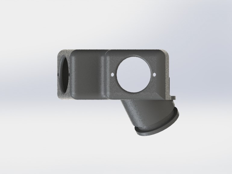
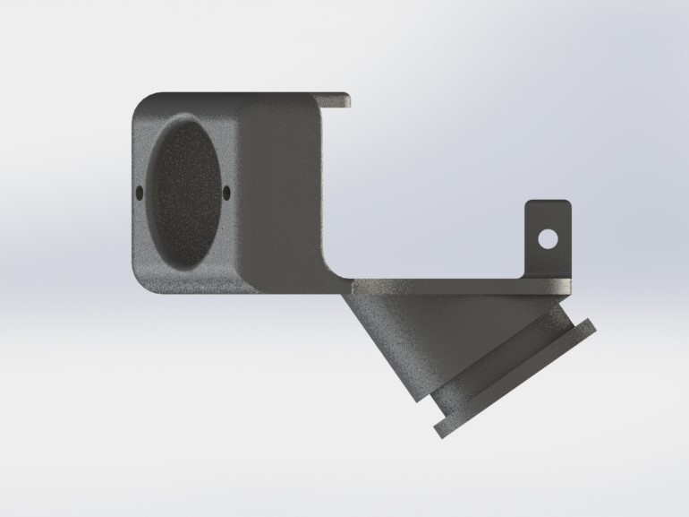
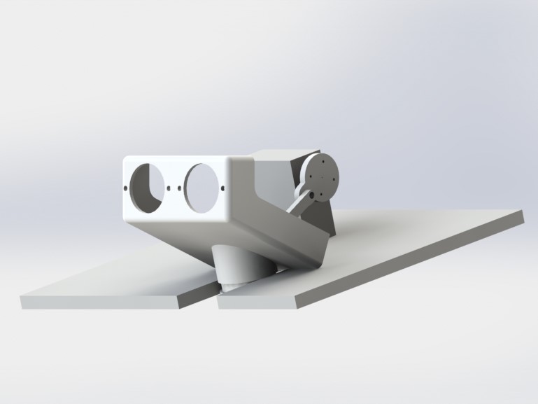
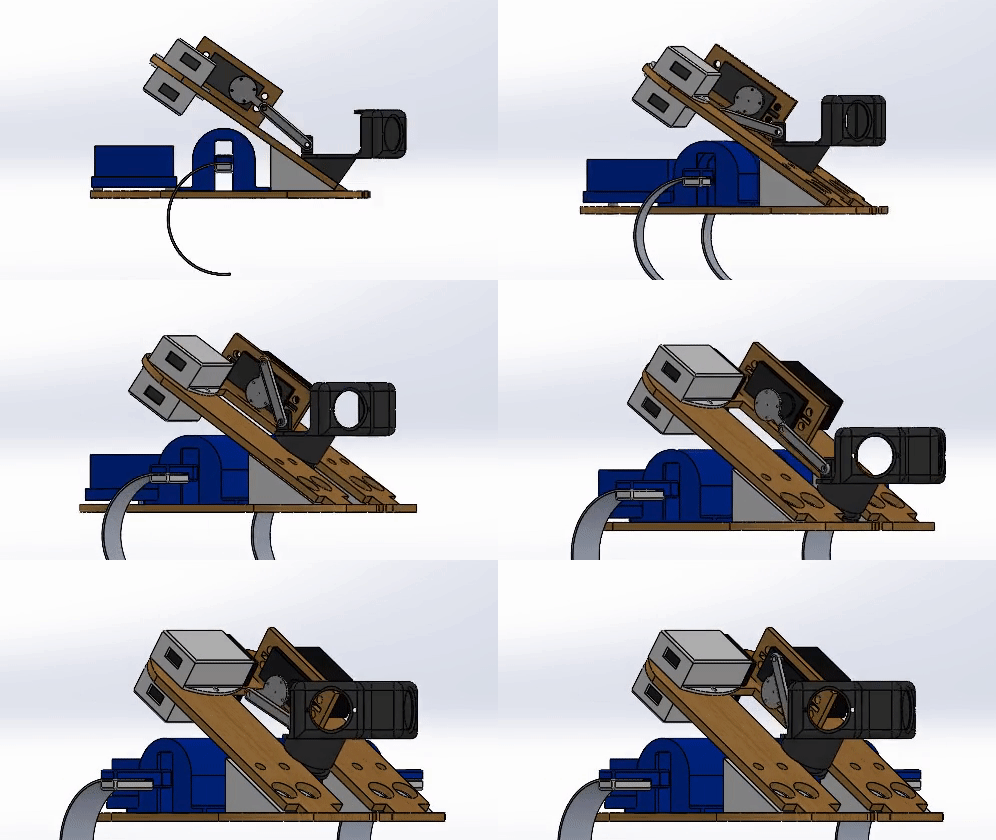
The head retraction movement of our hermit crab is controlled by a slot slider mechanism. This consists of one head (which acts as a sensor mount), two linkages, and a servo. The head is supported by a “neck” at a 35 degree angle: this way, the sensors are parallel with the ground when mounted on our angled frame. This “neck” allows .1” of clearance in the slot both along the diameter of the neck and the height of the neck. There is also a linkage mount on the back of the head. The linkages and head are 3D printed and the servo mount is laser-cut from Eucaboard. The linkages are connected to each other using screws and locknuts, and one linkage is connected to the servo with the use of a servo horn screwed into the linkage.
Component Mounts
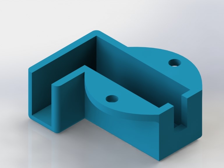
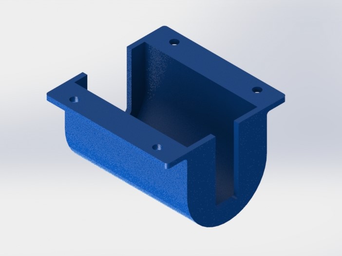
Component mounts were carefully measured and 3D printed to keep everything secure. We created mounting fixtures for the DC motors, 9V batteries, aluminum legs, and the servo motor. We also designed the base plate with holes for the photoresistor and mounting screws for the caster wheels and Arduino Uno. All of the components were carefully assembled to have low clearances and pack everything in as tight of a package as possible.
Challenges & Trade-offs
Throwing
One of our original goals was to make our hermit crab durable enough to be thrown without significant damage. Because of time constraints, focusing on different things, and the sheer danger of throwing something so heavy and dense, we decided not to pursue this goal. Some durable shell options we explored were: injection molding a shell shape and lining the shell with composites, foam, or oobleck; creating a shell and covering it with little hooks that would act as springs to dampen impact force; and using vibration resistant washers when connecting anything to the frame of our robot.
Slot Slider
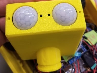
We began designing the slot slider mechanism in Sprint 2. Originally, the sensors were both facing forward. In the final design, they are 120 degrees apart to increase our hermit crab’s range of vision. We also considered designing this mechanism to also move the shell down over the head. We later determined that this was unnecessary. The final design also has a longer linkage connected to the servo (to increase the travel), is more space efficient, and has more clearance between parts (where the original design would interfere with other parts in the assembly).
Below, the original design is shown in the two left images. The final design, with the changes described, is shown in the rightmost image.
Design Sprint Progress
Sprint 1
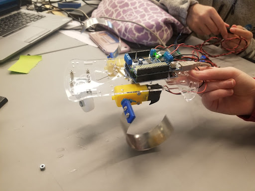
We started testing our hermit crab using motorized car kits from a previous mini-project in PIE. From here, we had our first taste of how important motor torque would be when speccing motors. The small DC motors that came with the kit proved to be too low torque to lift the weight of the electronics and other components using our compliant legs.
Sprint 2
In Sprint 2, we introduced the idea of using 2 baseplates to save space, allow the slot slider to slide up into the shell, and potentially allow for protecting more sensitive parts on the top baseplate (assuming they would be the most safe within the shell). When fabricating, we laser-cut what you see to the left. We then drilled holes into the baseplates where we needed them. We had some small problems with the holes not lining up properly, so we made sure to include holes with precise locations when we laser cut our final baseplate structure. In Sprint 2, we also produced the angle between the two base plates with a third wall that held up the end of the angled baseplate. In our final product, we used a triangle with nuts and bolts to hold the angled base plate up. We also added the servo mount.
Our biggest road block in Sprint 2 was discovering that our N20 gearmotors did not have enough torque to support our robot's weight. Also, one of the two that we bought did not work. Thus, we were not able to get a full system up and running until Sprint 3.
Sprint 3
Much of our development in Sprint 3 centered around building new components to accomodate our new, larger motors. Our first motors were very small N20 geared motors, and we switched to much larger 12V geared motors. The original motor mount design is seen to the upper left, and its iteration is shown to the lower left.
In Sprint 2, our leg mounts were two halves, which were press-fit onto the motor shafts. In Sprint 3, we used a set screw to secure the leg mount to the motor, as the D shaft was much less pronounced on the new motors. The leg mounts are shown to the right.
By the end of Sprint 3, our robot was essentially completely done except for some aesthetic pieces like the top hat.
